How a Liquid Cooling Loop Works: Manifold, Cold Plate and CDU
How a liquid cooling loop works — manifold, cold plate and CDU enclosure, and the custom parts in each stage.
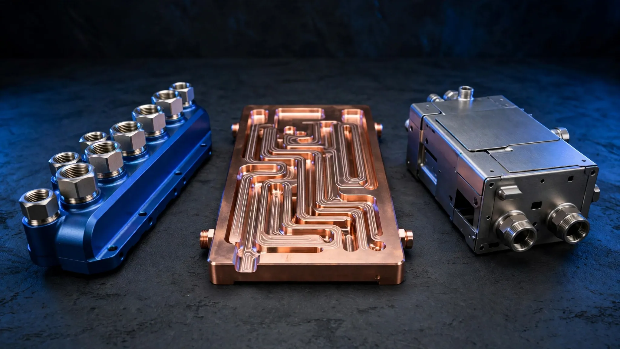
A liquid cooling loop has three stages: the manifold distributes coolant, the cold plate moves heat off the hardware, and the CDU enclosure houses the coolant distribution unit. Each stage is made of custom parts — machined and formed to your drawing.
Manifold
Manifold bodies distribute coolant through the loop. They are machined to your drawing, with connector and port parts fitted to the loop.
Cold plate
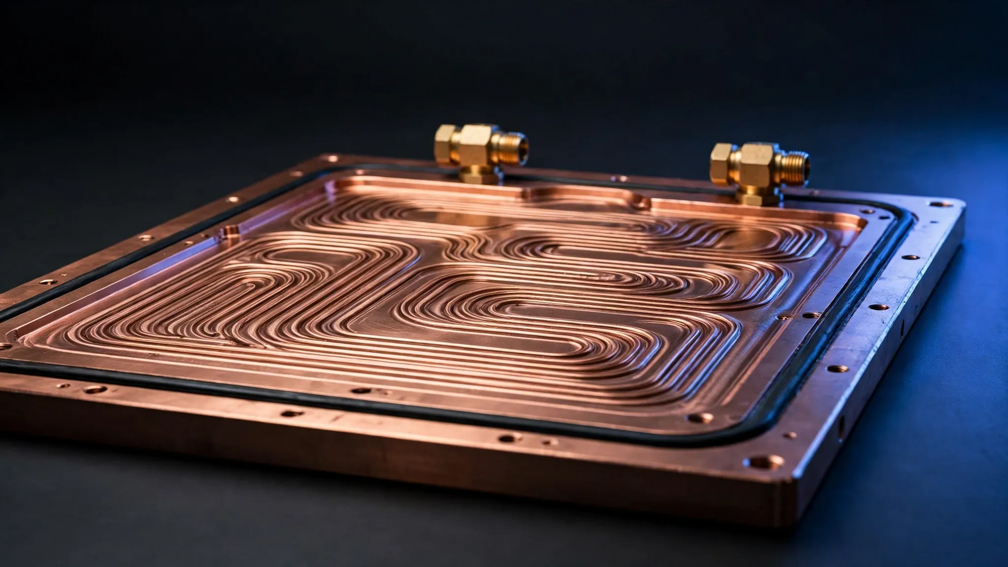
Cold plate bases and covers transfer heat from the hardware. Flatness and finish of sealing surfaces matter here — specify them on your drawing.
CDU enclosure
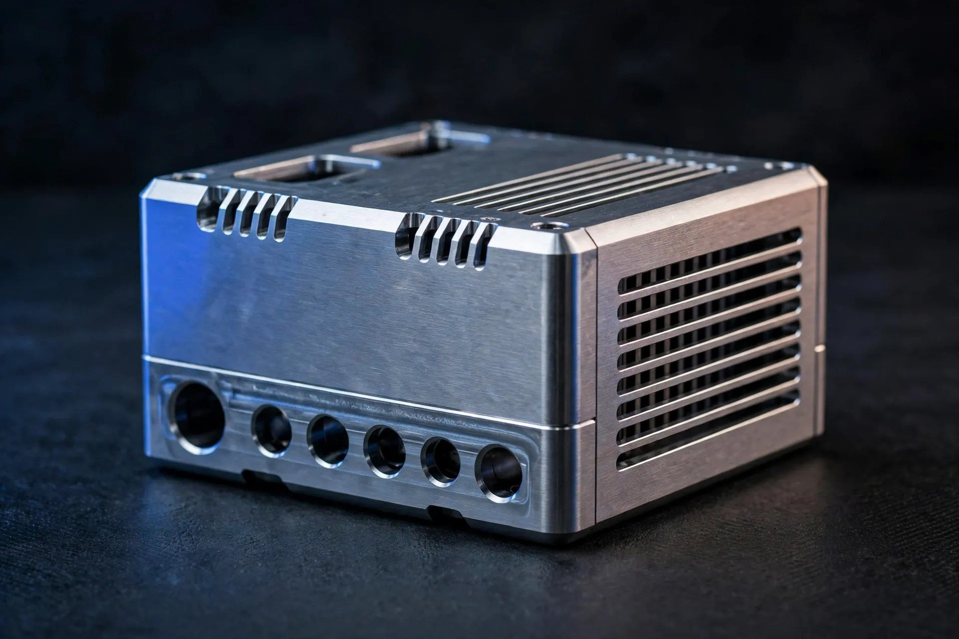
Sheet metal enclosures house the coolant distribution unit. Covers, panels and lids are made to fit the unit they go into.
Parts in the loop
Manifold bodies, cold plate bases, cold plate covers and sealing plates, CDU sheet metal enclosures, manifold mounting brackets, sealing and gasket parts, connector and port parts, covers and panels — all made to your drawing, no standard models, no stock parts.
Materials
Aluminium, copper and stainless steel as the drawing requires. Copper for cold plates and thermal parts; aluminium for manifolds, enclosures and covers; stainless steel for brackets and structural parts.
What to specify on your drawing
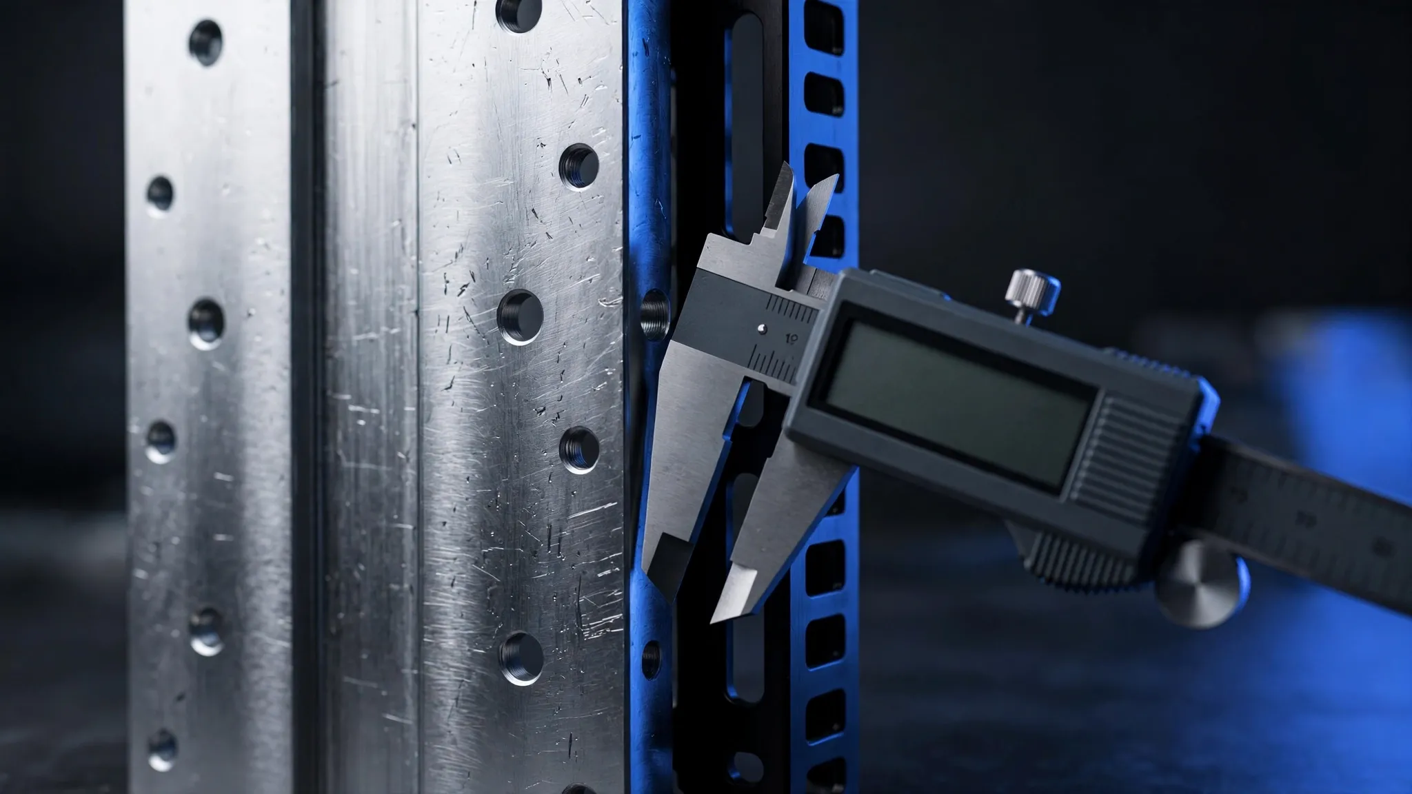
Material, key tolerances, flatness of sealing surfaces, and surface finish. Any test requirement should be specified on your drawing. Parts are made and inspected to your drawing — and shipped for export.
See: Custom Liquid Cooling Components · Parts & Applications